To document the Tado API, I needed to intercept the calls the mobile app was making to the server. As with many apps these days, the connection from the app to the server is encrypted using transport layer security (TLS) which makes it hard to read (that’s the point!). It is still possible to intercept and read this sort of traffic with a man-in-the-middle attack though: this post discusses how to do it.
How HTTPS works
Firstly, how does HTTP work? The normal transport protocol used for a web browser or RESTful API client to request pages or invoke API calls is HTTP. HTTP requests are not encrypted and can therefore be relatively easily intercepted by just routing the traffic via a simple proxy. A simple HTTP request for my home page would look like:
This request, and the response (such as a web page) can easily be read “off the wire”. For HTTPS, the client (e.g. the app on the phone) sends an unencrypted HTTP CONNECT message to the server, only revealing to the world the server that the client wishes to connect to. For instance:
At this point, the transport layer security (TLS) encryption handshake begins which creates a secure channel between the client and the server. Any subsequent requests from the client asking for e.g. specific web pages or API endpoints and perhaps containing a password are therefore encrypted and not readable.
The TLS handshake is underpinned by public key infrastructure (PKI) cryptography. The server presents an “X.509” certificate (think of it as being official like a birth certificate, not an every-day bronze swimming certificate) containing its name (e.g. my.tado.com) and the certificate is signed by a certificate authority (e.g. GoDaddy). Your web browser and your phone have built in lists of trusted certificate authorities (CAs). If the authority who signed the server’s certificate is one of the ones on your trusted CA list, and the name on the certificate is the site you were trying to connect to then the client continues and an encrypted channel is created.
If you are interested, you can read more about how certificates work in an earlier post about logging.
If you are connected to a website in a web browser on a computer, you can of course see all the HTTPS traffic by just opening the developer mode (often via F12). You can see the traffic because the web browser is at the end of the channel and is encrypting and decrypting it anyway for input and display purposes. It is when you need to see the traffic going to and from a client such as a mobile app which does not have a developer mode that you need to try harder.
Intercepting HTTPS
How then can HTTPS traffic be intercepted? Doing so is what is known as a “man in the middle” or MITM attack. Executing such an attack without the client’s knowledge is difficult (thank goodness) but as we are essentially trying to attack ourselves we can make it easier. There are a few pieces of software that can help with this: I used the Burp Suite but I also came across Charles proxy, mitmproxy and Fiddler which I believe can all do the same job.
What we need to do is route the traffic from the app to one of these proxies and from there to the original destination. For HTTP traffic the proxy can just pass on the requests and pass back the responses. For HTTPS traffic the proxy has to pretend to be the site you are trying to securely access. For instance:
- Client sends CONNECT to my.tado.com but is routed via the proxy.
- Proxy creates a new signed certificate claiming it is my.tado.com. The certificate is signed by a built-in fake certificate authority.
- Client rejects connection because it doesn’t trust the fake CA.
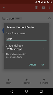
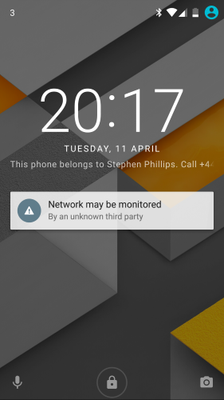
So, not only does the proxy have to pretend to be the secure site, the client has to be told to trust the fake CA. On phones and web browsers it is possible to add additional trusted CAs, so the fake CA certificate can be exported from e.g. Burp Suite and installed in the phone. As soon as you do this on an Android phone though, you get a permanent notification on your phone warning you that your communications may be insecure.
Once this fake CA is trusted by the phone, we can imagine trying this again:
- Client sends CONNECT to my.tado.com but is routed via the proxy.
- Proxy creates (on the fly) a new signed certificate claiming it is my.tado.com. The certificate is signed by a built-in fake certificate authority.
- Client examines the certificate and verifies that it trusts the (fake) CA which signed it and that the server name matches the one it is connecting to.
- A TLS connection is created between the client and the proxy.
- The client requests some data from my.tado.com over the secure channel to the proxy.
- At this point, or perhaps a little before, the proxy creates an HTTPS connection to my.tado.com
- The proxy receives the request from the client, decrypts it and logs it, then re-encrypts it and makes the same request to my.tado.com
- The proxy receives the response from my.tado.com, decrypts it and logs it, then re-encrypts it and sends it back to the client.
In this way, all the requests from and responses to the app on the phone can be logged and examined in the proxy software.
Routing traffic through the proxy
Setting up my network to route the traffic through the proxy while still allowing family members to use the LAN and the internet was the hardest part for me. I’ll explain what I did, and though it is quite specific I hope that it will help someone with some similar components.
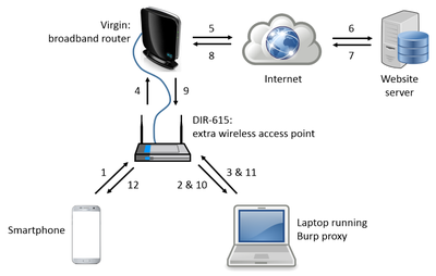
The diagram below shows the network connections involved and numbers the data-flow sequence. I had a spare D-Link DIR-615 wireless router lying around on which I had already installed DD-WRT: as DD-WRT provides shell access to the routing tables, I knew that I should be able to configure it to achieve what I wanted so I configured it to provide a “phillips-test” Wi-Fi network and wired it via an ethernet cable to the Virgin Media broadband router that serves my household.
Once it is all configured the sequence is as follows:
- Smartphone, connected to the phillips-test Wi-Fi, makes HTTPS request to the website.
- The DIR-615 routes the request to the laptop.
- Burp decrypts the request, logs it, encrypts it and sends it back over Wi-Fi to the DIR-615.
- This time, the router passes the request on to the Virgin Media broadband router.
- The router sends it out to the internet.
- The message is routed through to the website’s server.
- The response goes back to over the internet and into the Virgin network.
- The message comes back to the Virgin router.
- The router, knowing where the request came from, sends the response back to the DIR-615.
- The DIR-615 routes the message to the laptop.
- Burp decrypts the response, logs it, encrypts it and sends it back over Wi-Fi to the DIR-615.
- The DIR-615 sends the response back to the smartphone.
Basic configuration for the DIR-615
Please note, you don’t have to have a DIR-615 to do this, just a Wi-Fi router running DD-WRT or some similar hackable firmware. The DIR-615 just happens to be cheap, common and capable.
First you have to configure the DIR-615 so that devices can connect to it over Wi-Fi and access the internet. There are various ways to do that. First of all I tried the DD-WRT instructions for setting up a Wireless Access Point. I might have got confused here, but I think that maybe using a simple configuration such as that disables some of the other features that are needed for the routing described above: it got the devices on the internet but I couldn’t make any progress on reconfiguring the routing. Instead, I configured the DD-WRT to be on a different subnet. I can’t recall all the settings I changed but I think the following are the key ones:
Setup / Basic Settings tab
Setup / Advanced Routing tab
Wireless / Basic Settings tab
Services / Services tab
My primary Virgin Media router has an IP address of 192.168.0.1 and has a DHCP range starting at 192.168.0.100 so this doesn’t interfere with the static IP address set for the DIR-615. With this configuration I was able to connect my laptop and phone to the “phillips-test” Wi-Fi network and access the internet. Access from the phone to the website would be as in the diagram but skipping from step 1 directly to 4 on the way out and step 9 to 12 on the way back.
Advanced routing configuration for DIR-615
As a router is used, it builds up table of routes to use for different messages. Again, I am not completely sure here, but I found that I needed to do the next piece of configuration straight after rebooting the DIR-615 which would clear out any existing routing tables. Once rebooted, I connected to “phillips-test” from my laptop, noted down the IP address the laptop has been assigned (192.168.5.113 below) and then used the telnet program to get a shell on the router (e.g. telnet 192.168.5.1, username “root”, password whatever you chose).
The technique I used is taken from some instructions for setting up the Squid proxy as a transparent proxy. Section 6.1 on that page (the “First method”) worked for me. It suggests:
# iptables -t nat -A PREROUTING -i eth0 -s ! squid-box -p tcp --dport 80 -j DNAT --to squid-box:3128
# iptables -t nat -A POSTROUTING -o eth0 -s local-network -d squid-box -j SNAT --to iptables-box
# iptables -A FORWARD -s local-network -d squid-box -i eth0 -o eth0 -p tcp --dport 3128 -j ACCEPT
The iptables command defines the rules applied to the packets of data travelling through the router. The command can be used to set up an effective firewall for instance by dropping packaets that could be dangerous. I found some really good iptables documentation which explains everything. If you want to look at it, the situation we have here is described in table 6.3, the right-hand leg of the diagram and the “Nat table” section further down.
To translate the three proposed rules to our situation, squid-box is the IP address of the laptop and iptables-box is the IP address of the DIR-615 router. More than that needs changing though as all three of these commands refer to the interface eth0 to apply the rule to. eth0 is the label generally assigned to the single ethernet port typically found on a computer, but a router is more complex than that. If you execute the ifconfig command on the router you will get something like:
root@dd-wrt-test:~# ifconfig
br0       Link encap:Ethernet  HWaddr 00:24:01:AA:26:A8
          inet addr:192.168.5.1  Bcast:192.168.5.255  Mask:255.255.255.0
          UP BROADCAST RUNNING MULTICAST  MTU:1500  Metric:1
          RX packets:1056 errors:0 dropped:66 overruns:0 frame:0
          TX packets:933 errors:0 dropped:0 overruns:0 carrier:0
          collisions:0 txqueuelen:0
          RX bytes:190365 (185.9 KiB)  TX bytes:376623 (367.7 KiB)

br0:0     Link encap:Ethernet  HWaddr 00:24:01:AA:26:A8
          inet addr:169.254.255.1  Bcast:169.254.255.255  Mask:255.255.0.0
          UP BROADCAST RUNNING MULTICAST  MTU:1500  Metric:1

eth2      Link encap:Ethernet  HWaddr 00:24:01:AA:26:A8
          UP BROADCAST RUNNING MULTICAST  MTU:1500  Metric:1
          RX packets:21280 errors:0 dropped:0 overruns:0 frame:0
          TX packets:1052 errors:0 dropped:0 overruns:0 carrier:0
          collisions:0 txqueuelen:1000
          RX bytes:4081103 (3.8 MiB)  TX bytes:210740 (205.8 KiB)
          Interrupt:5

lo        Link encap:Local Loopback
          inet addr:127.0.0.1  Mask:255.0.0.0
          UP LOOPBACK RUNNING MULTICAST  MTU:16436  Metric:1
          RX packets:0 errors:0 dropped:0 overruns:0 frame:0
          TX packets:0 errors:0 dropped:0 overruns:0 carrier:0
          collisions:0 txqueuelen:0
          RX bytes:0 (0.0 B)  TX bytes:0 (0.0 B)

ra0       Link encap:Ethernet  HWaddr 00:24:01:AA:26:AA
          UP BROADCAST RUNNING MULTICAST  MTU:1500  Metric:1
          RX packets:43760 errors:0 dropped:0 overruns:0 frame:0
          TX packets:2065 errors:0 dropped:0 overruns:0 carrier:0
          collisions:0 txqueuelen:1000
          RX bytes:12112286 (11.5 MiB)  TX bytes:410992 (401.3 KiB)
          Interrupt:6

vlan1     Link encap:Ethernet  HWaddr 00:24:01:AA:26:A8
          UP BROADCAST RUNNING MULTICAST  MTU:1500  Metric:1
          RX packets:0 errors:0 dropped:0 overruns:0 frame:0
          TX packets:203 errors:0 dropped:0 overruns:0 carrier:0
          collisions:0 txqueuelen:0
          RX bytes:0 (0.0 B)  TX bytes:27822 (27.1 KiB)

vlan2     Link encap:Ethernet  HWaddr 00:24:01:AA:26:A9
          inet addr:192.168.0.5  Bcast:192.168.0.255  Mask:255.255.255.0
          UP BROADCAST RUNNING MULTICAST  MTU:1500  Metric:1
          RX packets:21263 errors:0 dropped:1843 overruns:0 frame:0
          TX packets:849 errors:0 dropped:0 overruns:0 carrier:0
          collisions:0 txqueuelen:0
          RX bytes:3697347 (3.5 MiB)  TX bytes:176166 (172.0 KiB)
I thought initially that each ethernet port on the router would be a separate interface but that’s not the case. While I was puzzling this out, I found a useful block diagram of the interfaces of a similar router. The numbers of the interfaces are one out compared to the above but I think it’s basically the same. The thing to look for in the output of the ifconfig command is which interface has the local IP address assigned to it: the one used on the test Wi-Fi subnet (192.168.5.1 here). In this case it is br0 and it is through that interface that all message to and from the Wi-Fi network pass. The other IP address (192.168.0.5) - the DIR-615 as seen from the main network - is assigned to vlan2 corresponding to the WAN port (or vlan1 in the diagram).
So, adjusting for the interface name and the IP addresses, the following iptables commands are then needed:
# iptables -t nat -I PREROUTING -i br0 -s ! 192.168.5.113 -p tcp --dport 80 -j DNAT --to 192.168.5.113:3128
# iptables -t nat -I POSTROUTING -o br0 -s 192.168.5.0/24 -d 192.168.5.113 -j SNAT --to 192.168.5.1
# iptables -I FORWARD -s 192.168.5.0/24 -d 192.168.5.113 -i br0 -o br0 -p tcp --dport 3128 -j ACCEPT
The first rule says:
This will make sure that a request from the phone to the website ends up arriving at the laptop instead.
The second rule says:
This means that the messages coming from the smartphone and being redirected to the laptop will have their replies sent back to the DIR-615 rather than directly to the phone. This is how NAT (network address translation) works. Normally NAT is used when there are many computers using a single network connection (just like many devices in the home sharing the broadband connection). The home devices have IP addresses such as 192.168.0.x, the router replaces the source address with its own WAN IP address and the replies come back to the router which keeps track of which device to route the reply to.
As it says in the Squid documentation, the third rule may not be necessary. It just says to make sure that anything from the Wi-Fi network, to the Wi-Fi network with the destination of the laptop is accepted (not dropped).
Those three rules together will divert HTTP traffic via the laptop, but we are actually interested in HTTPS traffic which uses port 443 so two more rules are needed to redirect that traffic to port 3129 on the laptop:
# iptables -t nat -I PREROUTING -i br0 -s ! 192.168.5.113 -p tcp --dport 443 -j DNAT --to 192.168.5.113:3129
# iptables -I FORWARD -s 192.168.5.0/24 -d 192.168.5.113 -i br0 -o br0 -p tcp --dport 3129 -j ACCEPT
Ports 3129 and 3129 are not significant by the way, they are just the ones chosen by the Squid proxy people. Most numbers over 1024 would do.
Once those commands have been run, the iptables for the NAT chains look like so (for me at least):
# iptables -t nat --list -v
Chain PREROUTING (policy ACCEPT 1175 packets, 227K bytes)
 pkts bytes target     prot opt in     out     source               destination
    0     0 DNAT       tcp  --  br0    any    !laptop               anywhere            tcp dpt:https to:192.168.5.113:3129
    0     0 DNAT       tcp  --  br0    any    !laptop               anywhere            tcp dpt:www to:192.168.5.113:3128
    0     0 DNAT       icmp --  any    any     anywhere             192.168.0.5         to:192.168.5.1
   70  7541 TRIGGER    0    --  any    any     anywhere             192.168.0.5         TRIGGER type:dnat match:0 relate:0

Chain INPUT (policy ACCEPT 470 packets, 37155 bytes)
 pkts bytes target     prot opt in     out     source               destination

Chain OUTPUT (policy ACCEPT 122 packets, 12227 bytes)
 pkts bytes target     prot opt in     out     source               destination

Chain POSTROUTING (policy ACCEPT 121 packets, 11899 bytes)
 pkts bytes target     prot opt in     out     source               destination
    1   328 SNAT       0    --  any    br0     192.168.5.0/24       laptop              to:192.168.5.1
   77  5806 SNAT       0    --  any    vlan2   192.168.5.0/24       anywhere            to:192.168.0.5
    0     0 MASQUERADE  0    --  any    any     anywhere             anywhere            mark match 0x80000000/0x80000000
In the PREROUTING chain the first two rules are the ones we added. In the “source” column you can see !laptop: this will not say laptop, rather it will be the local name of that machine on the network. In the POSTROUTING chain the first rule is the one we added: changing the source address to be the DIR-615. The second rule is the standard NAT rule saying that for any messages going out on the WAN port (to the main network), replace the source address with the DIR-615’s WAN address so that the replies will come back.
The next command checks that the FORWARD rule is there:
# iptables --list -v
Chain INPUT (policy ACCEPT 0 packets, 0 bytes)
 pkts bytes target     prot opt in     out     source               destination
  599 66495 ACCEPT     0    --  any    any     anywhere             anywhere            state RELATED,ESTABLISHED
    0     0 DROP       udp  --  vlan2  any     anywhere             anywhere            udp dpt:route
  etc

Chain FORWARD (policy ACCEPT 0 packets, 0 bytes)
 pkts bytes target     prot opt in     out     source               destination
    0     0 ACCEPT     tcp  --  br0    br0     192.168.5.0/24       laptop              tcp dpt:3129
    0     0 ACCEPT     tcp  --  br0    br0     192.168.5.0/24       laptop              tcp dpt:squid
  etc
Both the ACCEPT rules are there and port 3128 is replaced with squid as it is well known that squid uses it.
Configuring Burp on the laptop
For reference, I used Burp Suite Free Edition for Windows, v1.7.16.
- Go to the proxy tab and in there, the options tab.
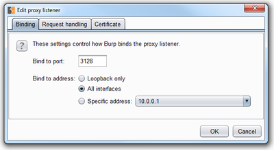
- Click on “Add” in the Proxy Listeners section and the “Add a new proxy listener” window pops up (see first screenshot below).
- In the “Binding” tab:
- bind to port: 3128
- bind to address: “All interfaces” (it’s just easier)
- In the “Request handling” tab:
- tick “Support invisible proxying”
- Click on “OK” to close the window.
- Add proxy listener for 3129 in the same way.
- Deselect default proxy on 127.0.0.1:8080
Intercepting
Once Burp is configured this way, the router is configured as described and the Burp CA is installed on the smartphone then all HTTP and HTTPS traffic will start to appear in the “Proxy” / “Intercept” tab in Burp. Each time a message comes through you have to click to let it pass (after editing it if you want to) or drop it. If you want, you can configure the proxy to only intercept certain types of traffic so that there’s less clicking to do.
One final tip: turn off mobile data on the phone to make sure tha the traffic goes over the test Wi-Fi network.
Things that didn’t work
While trying to get the iptables commands to work, I also tried the second method in the Squid documentation, i.e.
# iptables -t mangle -A PREROUTING -j ACCEPT -p tcp --dport 80 -s squid-box
# iptables -t mangle -A PREROUTING -j MARK --set-mark 3 -p tcp --dport 80
# ip rule add fwmark 3 table 2
# ip route add default via squid-box dev eth1 table 2
I thought it worth noting, that whilst I understand this ruleset and can see it would work, it didn’t work for me. The ip command is part of the iproute2 toolkit. What frustrated me most was that it turns out that the version of ip built into DD-WRT does not include the ip rule show command (in order to save space) which makes checking what rules you’ve entered impossible. Unfortunately, no error is shown either, just no output. Once I realised that, I gave up on that method.


Comments
Comments powered by Disqus